
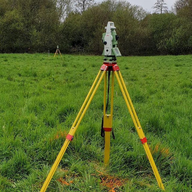

What is a Topographical Survey?
A topographical survey, also known as a land survey or a topo survey, is a surveying method used to gather detailed information about the physical features and characteristics of a piece of land or a specific area. It involves measuring and mapping various natural and man-made features on the land's surface.
The primary purpose of a topographical survey is to accurately represent the three-dimensional shape and configuration of the land, including its elevations, contours, and other significant features. The survey provides a comprehensive understanding of the existing terrain, which is crucial for planning, design, and construction of infrastructure, development projects, land management, and various other applications.
During a Cadmap topographical survey, surveyors use a combination of traditional and modern surveying techniques and equipment. This can include the use of total stations, GPS (Global Positioning System) receivers, aerial photogrammetry, laser scanning, and other advanced instruments.
The surveyors traverse the land, taking precise measurements at various points to establish the elevation and position of key features such as buildings, roads, trees, rivers, fences, utility infrastructure, and any other relevant elements. The collected data is then processed and analyzed to generate accurate topographical maps, plans, and digital models, which typically include contour lines, spot heights, and other annotations to depict the land's characteristics.
Topographical surveys in the UK are essential for a range of purposes, including urban planning, engineering design, construction projects, environmental assessments, land development, property boundary determination, and more. They provide critical information for decision-making, visualization, and analysis of the land, ensuring that any proposed development or modification takes into account the existing conditions and constraints of the site.
If you require a Topographical Survey please contact Cadmap - Company Email : info@cadmap.co.uk
What is a PAS128 GPR Survey?
A PAS 128 Utility Survey in the UK is a type of survey that aims to locate and map underground utility infrastructure within a specified area. PAS128 stands for Publicly Available Specification 128, which is a specification developed by the British Standards Institution (BSI) for the detection, verification, and location of underground utilities.
The purpose of a PAS128 Utility Survey is to provide accurate and reliable information about the location, depth, and nature of buried utility services, such as water pipes, gas lines, electric cables, telecommunications networks, drainage systems, and other underground assets. This information is essential for planning and design purposes, ensuring safe excavation, reducing the risk of utility strikes, and minimizing costly delays or disruptions during construction projects.
A PAS128 Utility Survey typically involves the following steps:
Desktop Study: A thorough review of available records, as-built drawings, historical maps, and utility plans is conducted to gather existing information about the potential presence and location of utilities within the survey area.
Site Reconnaissance: Surveyors visit the site to visually identify visible utility features, such as manholes, valve covers, utility cabinets, and other surface-level indications of underground services. This helps in understanding the site context and identifying areas of potential utility presence.
Geophysical Survey: Various geophysical techniques are used to detect and locate underground utilities. These techniques can include Ground Penetrating Radar (GPR), electromagnetic induction (EMI) or electromagnetic locating (EML) devices, magnetic methods, and other specialized tools. These instruments help identify anomalies and subsurface features that may indicate the presence of utilities.
Utility Verification: Once potential utility features are identified through geophysical methods, further investigation and verification are conducted to confirm the type, size, depth, and condition of the utilities. This may involve manual digging, potholing, or other non-destructive techniques to expose and visually inspect the utility assets.
Data Processing and Reporting: The collected data from the PAS128 Utility Survey is processed, analyzed, and compiled into a comprehensive report or deliverables. The report provides detailed information about the identified utilities, including their location, depth, material, condition, and other relevant attributes.
PAS128 Utility Surveys are important for managing the risks associated with underground utilities, ensuring compliance with regulations, and promoting safe construction practices. They help project teams make informed decisions, plan excavation activities, and mitigate the potential risks of utility strikes, ultimately improving project efficiency and reducing costs.
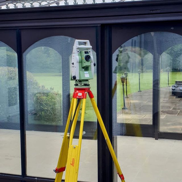
What is a Measured Building Survey?
A measured building survey is a detailed survey conducted to accurately measure and capture the physical dimensions and features of an existing building. The survey provides precise measurements and data about the building's structure, layout, and architectural elements. Measured building surveys are commonly used for a variety of purposes, including renovation, refurbishment, space planning, and architectural design.
During a measured building survey, surveyors utilize various surveying techniques and instruments to collect accurate measurements of the building's interior and exterior. These measurements can include floor plans, elevations, sections, and other relevant details. The surveyors may use tools such as laser distance meters, total stations, 3D laser scanners, and handheld measurement devices to capture the required data.
The survey typically covers elements such as walls, partitions, doors, windows, staircases, columns, beams, and any other architectural features that need to be documented. The measurements are usually taken at regular intervals or grid points throughout the building to ensure comprehensive coverage.
Once the data is collected, it is processed and used to create detailed drawings, plans, or 3D models of the building. These deliverables provide an accurate representation of the building's dimensions, layout, and features, allowing architects, engineers, and designers to work with precise information during the planning and design stages of a project.
Measured building surveys are valuable for a range of applications, including architectural design, building renovations, heritage conservation, space optimization, property management, and compliance with building regulations. The surveys provide a foundation of accurate and reliable data to facilitate informed decision-making and efficient project execution.
If you require a Measured Building Survey please contact Cadmap - Company Email : info@cadmap.co.uk
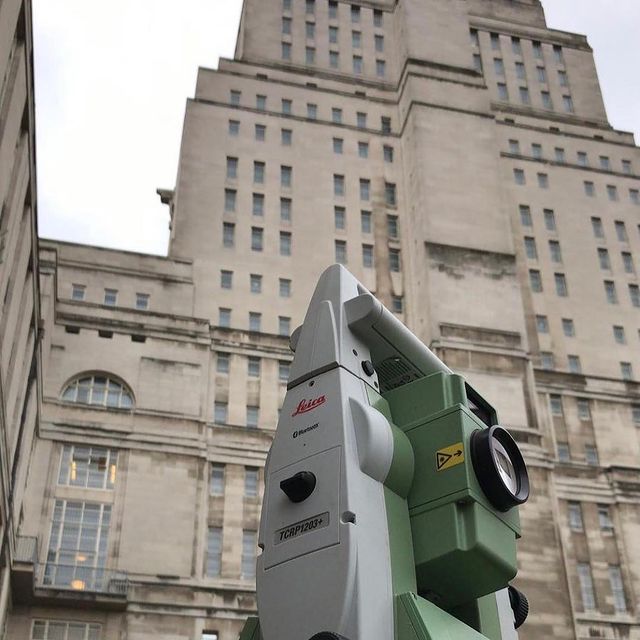
What is a Building Movement Monitoring Survey?
A Structural Monitoring Survey is a specialized surveying technique that involves the continuous or periodic monitoring of structural elements, such as buildings, bridges, dams, towers, or any other infrastructure, to assess their behavior, stability, and integrity over time. The survey aims to identify and track any changes, movements, or deformations that may occur in the structure.
Structural monitoring surveys typically involve the use of various sensors, instruments, and data acquisition systems strategically placed on or within the structure being monitored. These sensors can measure parameters such as:
- Displacement: Measuring the movement or displacement of specific points or areas of the structure.
- Strain: Monitoring the stress and strain levels within structural components.
- Load: Monitoring the applied loads or forces on the structure, such as wind, vibration, or traffic loads.
- Vibration: Assessing the dynamic response and vibration characteristics of the structure.
- Crack Monitoring: Monitoring the development or widening of cracks in structural elements.
The collected data from the sensors is recorded and analyzed over time to identify any changes or anomalies that may indicate structural issues, deterioration, or movement beyond acceptable limits. This information can help engineers and stakeholders make informed decisions regarding maintenance, repair, or reinforcement strategies to ensure the safety and longevity of the structure.
Structural monitoring surveys are particularly valuable for critical infrastructure, high-rise buildings, historic structures, and areas prone to seismic activity. They provide real-time or periodic insights into the structural behavior and performance, allowing for early detection of potential problems and the implementation of timely corrective measures.
The surveying methods used in structural monitoring may vary depending on the specific requirements of the structure and the desired level of monitoring detail. These methods can include geodetic surveying, remote sensing, strain gauges, tiltmeters, accelerometers, and other specialized sensors and instruments.
If you require a Monitoring Survey please contact Cadmap - Company Email : info@cadmap.co.uk
What is a Site Setting Out Survey?
Site engineering setting out refers to the process of establishing and marking the precise positions and dimensions of proposed structures or features on a construction site. It involves translating the design plans and specifications onto the actual site to guide the construction process accurately.
The setting out process is typically performed by site engineers or surveyors who use specialized surveying equipment and techniques to ensure that the construction activities align with the intended design. The primary objectives of site engineering setting out are:
Positioning Structures: The surveyor sets out the positions of buildings, roads, utilities, foundations, structural elements, and other components according to the design plans. This involves marking points, lines, and reference points on the ground to guide the construction team during the building process.
Aligning and Leveling: The surveyor establishes the correct alignment and level of various structural elements to ensure they are positioned accurately and in accordance with the design. This includes setting out centerlines, boundaries, and other critical reference lines.
Checking Dimensions: The surveyor verifies the dimensions and measurements specified in the design plans. This may involve measuring distances, angles, heights, and other critical dimensions to ensure they match the design requirements.
Controlling Levels and Gradients: The surveyor establishes the required levels and gradients for the construction elements, such as roads, drainage systems, and platforms. This ensures proper drainage, accessibility, and conformity to design specifications.
Quality Control: Site engineering setting out helps ensure that construction activities are executed to the required standards and tolerances. It allows for the early detection and correction of any discrepancies or errors in the construction process.
Site engineering setting out plays a crucial role in ensuring that the constructed elements align with the design intent, facilitating smooth construction operations, and minimizing errors or rework. It provides a reference framework for the construction team to work from and ensures that the final product meets the design requirements accurately.
To perform site engineering setting out, surveyors typically use surveying instruments like total stations, theodolites, levels, and GPS (Global Positioning System) equipment to accurately measure distances, angles, elevations, and positions on the construction site.
If you require a setting out job please contact Cadmap - Company Email : info@cadmap.co.uk
What is a Hydrographic Survey?
A hydrographic survey is a type of survey conducted in bodies of water, such as oceans, lakes, rivers, and harbors, to map and study the physical features, contours, and conditions of the water body and its submerged environment. The primary purpose of a hydrographic survey is to collect accurate and detailed information about the depth, shape, and composition of the underwater terrain.
Hydrographic surveys are conducted using specialized equipment and techniques to measure the bathymetry (underwater topography), water depths, currents, tides, and other related data. The collected information is used to create nautical charts, maps, and models that are essential for safe navigation, maritime operations, coastal engineering, environmental management, and various other marine-related activities.
The process of conducting a hydrographic survey typically involves the following steps:
Data Collection: Surveyors use specialized surveying instruments, such as multibeam echo sounders, single-beam echo sounders, side-scan sonar, and sub-bottom profilers, to collect depth measurements and other relevant data. These instruments emit sound waves or pulses that travel through the water column and bounce back from the seafloor, allowing for the calculation of water depths and the detection of underwater features.
Positioning and Georeferencing: Precise positioning is critical in hydrographic surveys. Global Navigation Satellite Systems (GNSS) and other positioning techniques, such as differential GPS (DGPS), are used to accurately determine the survey vessel's position and align the collected data with the Earth's coordinate system.
Data Processing and Analysis: The collected survey data is processed and analyzed using specialized software to filter out noise, eliminate errors, and generate accurate bathymetric charts, contour maps, and other outputs. Advanced algorithms are applied to handle data interpolation, quality control, and visualization.
Charting and Reporting: The processed survey data is used to update nautical charts and produce reports that provide important information for navigational safety, maritime infrastructure planning, environmental assessments, and resource management.
Hydrographic surveys are crucial for maritime navigation, port and harbor management, dredging operations, offshore installations, marine construction, underwater cable and pipeline routing, coastal zone management, and environmental monitoring. They help ensure the safety of maritime transportation, aid in the planning and design of marine structures, and contribute to the sustainable management of marine ecosystems.
If you require a Hydrographic Survey please contact Cadmap - Company Email : info@cadmap.co.uk
What is a BIM REVIT Model?
A BIM (Building Information Modeling) Revit model refers to a digital representation of a building or infrastructure project created using Autodesk Revit software. Revit is a powerful and widely used BIM tool that allows architects, engineers, and construction professionals to collaboratively design, visualize, simulate, and document building projects.
In a BIM Revit model, the building's geometry, structural elements, architectural components, mechanical and electrical systems, and other relevant information are integrated into a single digital model. This model serves as a central repository of information that can be accessed and shared by project stakeholders throughout the lifecycle of the project, from design and construction to operation and maintenance.
The BIM Revit model contains a rich set of data associated with each element or component, including its properties, dimensions, materials, performance characteristics, and relationships with other elements. This data enables more accurate and detailed design visualization, analysis, and coordination.
Some key features and benefits of a BIM Revit model include:
Integrated Design: The model allows for the simultaneous design and coordination of multiple disciplines, such as architecture, structure, and MEP (Mechanical, Electrical, and Plumbing), fostering collaboration and reducing conflicts or clashes in the design process.
3D Visualization: The model provides a 3D representation of the building, enabling stakeholders to visualize and explore the design from various angles, perspectives, and levels of detail.
Clash Detection: The model facilitates clash detection, where potential conflicts between different building systems or components can be identified and resolved before construction, reducing errors, rework, and delays.
Quantities and Cost Estimation: The model can generate accurate quantities and material takeoffs, supporting cost estimation, procurement, and project planning.
Construction Sequencing: The model can be used to simulate construction sequences and visualize the construction process, helping with project scheduling, logistics, and site coordination.
Facility Management: The BIM Revit model can serve as a foundation for facility management, allowing building owners and operators to access information about the building's components, maintenance schedules, and systems for efficient operation and maintenance.
Overall, a BIM Revit model enhances collaboration, improves design coordination, reduces errors, and provides a comprehensive digital representation of a building project, enabling stakeholders to make more informed decisions throughout the project lifecycle.
Why invest money into a Topographical Survey?
Cadmap Limited based in the UK, advise in 2024, having a topographical land survey carried out remains crucial for several reasons:
Urban Development: The UK continues to undergo urbanization and development projects, particularly in cities and urban areas. Topographical surveys are essential for understanding the existing landscape and planning for the construction of roads, buildings, utilities, and other infrastructure to support population growth and urban expansion.
Construction Projects: Topographical surveys are indispensable for architects, engineers, and construction professionals in designing and constructing structures that are compatible with the surrounding environment. The survey data helps determine land elevation, contours, and features, enabling precise construction planning and implementation while adhering to building regulations and standards.
Infrastructure Maintenance: Existing infrastructure in the UK, including roads, railways, bridges, and utilities, requires regular maintenance and upgrades. Topographical surveys assist in identifying areas requiring attention, such as erosion, subsidence, or changes in land features, facilitating proactive maintenance strategies to ensure the safety and longevity of infrastructure systems.
Environmental Management: With growing environmental concerns, topographical surveys play a vital role in assessing the impact of development on the natural landscape. They provide crucial information for environmental impact assessments, aiding in the identification and mitigation of potential risks to ecosystems, water bodies, and biodiversity.
Land Use Planning: Government agencies and local authorities rely on topographical surveys to make informed decisions about land use planning, zoning regulations, and conservation efforts. Understanding the characteristics of the land helps policymakers balance development with environmental protection and sustainable land management practices.
Property Transactions: During property transactions, topographical surveys provide essential information about property boundaries, easements, and potential hazards. Buyers, sellers, and lenders use this data to assess the value and suitability of the land, as well as to mitigate legal risks associated with property ownership.
Risk Assessment and Disaster Management: Topographical surveys help identify areas prone to natural disasters such as floods, landslides, and coastal erosion. This information is vital for emergency preparedness and response efforts, allowing authorities to develop mitigation strategies, evacuation plans, and infrastructure resilience measures to protect communities and infrastructure.
Overall, topographical land surveys are fundamental tools for land management, development, and conservation in the UK, providing accurate data that supports informed decision-making, sustainable practices, and the safeguarding of both natural and built environments.
Why invest money into a Measured Building Survey?
Cadmap Limited insist that having a measured building survey carried out remains essential for several reasons:
Property Development and Renovation: With the ongoing demand for housing and commercial properties, developers and investors require accurate information about existing buildings to make informed decisions regarding renovations, refurbishments, or new construction projects. Measured building surveys provide precise details about the dimensions, layout, and structural integrity of buildings, facilitating the planning and design process.
Architectural Design and Planning: Architects rely on measured building surveys to create accurate drawings and models of existing structures. This information is essential for designing extensions, alterations, or adaptations that integrate seamlessly with the existing building fabric while complying with building regulations and planning requirements.
Asset Management: Property owners, landlords, and facilities managers use measured building surveys to assess the condition of their assets and plan for maintenance, repairs, or upgrades. By understanding the current state of the building and identifying any defects or deficiencies, property owners can prioritize maintenance tasks and allocate resources effectively to ensure the long-term sustainability of their assets.
Historic Preservation and Conservation: In the UK, where historical architecture is abundant, measured building surveys play a crucial role in preserving and conserving heritage buildings. Detailed surveys help document the architectural features, materials, and construction techniques used in historic structures, aiding in restoration projects and ensuring that preservation efforts are carried out with precision and respect for heritage values.
Legal and Regulatory Compliance: Measured building surveys may be required to comply with various legal and regulatory requirements, such as planning applications, building control approvals, or property transactions. Survey data provides objective evidence of the building's condition and compliance with relevant standards, helping stakeholders navigate complex legal frameworks and avoid potential disputes or liabilities.
Health and Safety: Ensuring the health and safety of occupants is paramount in any building environment. Measured building surveys help identify potential hazards, such as structural weaknesses, fire risks, or accessibility issues, enabling property owners and managers to implement appropriate safety measures and comply with health and safety regulations.
Insurance and Risk Management: Insurance companies may require measured building surveys as part of the risk assessment process for underwriting property insurance policies. Accurate survey data helps insurers assess the value and risk profile of the building, determine appropriate coverage levels, and mitigate potential losses in the event of damage or liability claims.
Overall, measured building surveys are indispensable tools for property stakeholders in the UK, providing valuable information that supports decision-making, risk management, and compliance with legal and regulatory requirements in the built environment.
Why invest money into a Utility Mapping Survey?
In the UK in 2024, having a utility mapping survey carried out remains crucial for several reasons:
Infrastructure Planning and Development: As urban areas continue to grow and infrastructure projects expand, accurate utility mapping surveys are essential for planning new developments and ensuring that infrastructure networks, such as water, gas, electricity, telecommunications, and sewerage systems, are efficiently designed and implemented.
Preventing Accidents and Service Disruptions: Utility mapping surveys help identify the precise location and depth of underground utility lines and infrastructure, reducing the risk of accidental damage during construction, excavation, or maintenance activities. By avoiding utility strikes, potential service disruptions, injuries, and costly repairs can be prevented.
Compliance with Regulations: In the UK, there are strict regulations and guidelines governing the management and protection of underground utilities. Utility mapping surveys assist developers, contractors, and local authorities in complying with legal requirements, such as the Construction (Design and Management) Regulations and Health and Safety at Work Act, by providing accurate information about the location and condition of buried services.
Cost Savings and Efficiency: By accurately mapping underground utilities, construction projects can be planned more efficiently, minimizing the need for costly delays, redesigns, or utility relocations. Identifying conflicts or clashes with existing utilities early in the planning process allows for proactive solutions to be implemented, reducing project risks and avoiding costly disputes.
Environmental Protection: Accidental damage to underground utilities can have significant environmental consequences, such as pollution, groundwater contamination, or habitat destruction. Utility mapping surveys help mitigate these risks by ensuring that construction activities are conducted in a manner that minimizes environmental impact and complies with environmental regulations.
Emergency Response Planning: Utility mapping surveys provide critical information for emergency responders in the event of utility failures, leaks, or other emergencies. Knowing the precise location of underground utilities enables rapid and effective response efforts, minimizing the duration and severity of service disruptions and enhancing public safety.
Asset Management: Utility GPR mapping surveys support asset management practices by providing accurate data about the location, condition, and lifespan of underground infrastructure. This information helps utility companies and infrastructure owners prioritize maintenance, repairs, and replacement efforts, optimizing asset performance and longevity.
Overall, utility mapping surveys are essential tools for infrastructure planning, construction safety, regulatory compliance, cost management, environmental protection, emergency preparedness, and asset management in the UK, ensuring the efficient and sustainable management of underground utilities in an increasingly urbanized environment.
Why engage the services of a Land Surveying Company such as Cadmap Limited?
Expertise and Experience: Land surveying companies employ professionals with specialized training and experience in surveying techniques, regulations, and industry standards. Their expertise ensures accurate and reliable survey data for your project.
Legal Compliance: Land surveyors are familiar with local laws, regulations, and zoning requirements governing land use and development. Hiring a surveying company helps ensure that your project complies with all legal requirements, avoiding potential disputes, fines, or delays.
Accuracy and Precision: Surveying companies use state-of-the-art equipment and techniques to gather precise measurements of land features, boundaries, and topography. Accurate survey data is essential for making informed decisions and minimizing risks during project planning, design, and construction.
Risk Mitigation: Professional land surveyors identify potential risks and constraints on your property, such as easements, encroachments, or environmental hazards. By addressing these issues early in the project, you can mitigate risks and avoid costly setbacks or legal disputes later on.
Cost Savings: While hiring a surveying company involves upfront costs, it can save you money in the long run by preventing costly mistakes, design errors, or construction delays. Accurate survey data helps optimize project planning, reduce rework, and maximize the efficiency of construction activities.
Efficient Project Planning: Land surveyors provide essential information for project planning, including site analysis, feasibility studies, and design optimization. Their surveys help identify opportunities and constraints on your property, enabling you to develop realistic timelines, budgets, and project scopes.
Communication and Collaboration: Surveying companies work closely with architects, engineers, planners, and other project stakeholders to ensure seamless coordination and integration of survey data into the project workflow. Effective communication and collaboration streamline decision-making and improve project outcomes.
Professional Documentation: Land surveyors provide comprehensive reports, maps, and drawings documenting their survey findings. These documents serve as valuable reference materials for project stakeholders, regulatory agencies, and future property owners, enhancing transparency and accountability throughout the project lifecycle.
Peace of Mind: By hiring a reputable land surveying company, you gain peace of mind knowing that your project is in capable hands. Professional surveyors prioritize quality, integrity, and client satisfaction, ensuring that your project receives the attention and expertise it deserves.
Overall, hiring a land surveying company offers numerous benefits, including expertise, legal compliance, accuracy, risk mitigation, cost savings, efficient project planning, communication, documentation, and peace of mind. Whether you're planning a small-scale development or a large-scale infrastructure project, partnering with a surveying firm can help you achieve your goals with confidence.
If you require a BIM Revit Model please contact Cadmap - Company Email : info@cadmap.co.uk
Here are some of the clients Cadmap have worked alongside on various projects.
 https://geospatialsurveys.co.uk/

")

